Degreeing a Cam
The method for setting up your camshaft varies from one engine to another. In many cases you simply line up two dots and you're done. In other cases, you have to actually set the cam at an angle that is specified on the Cam Card. Why worry about anything else? You inspect other parts you purchase, why not inspect your camshaft? What do you do when there is no Cam Card? This page describes how to do a thorough job, so you can check the cam against its specs, determine whether its recommended settings are reasonable, and then set it up correctly
We believe you should go beyond basic cam set up and measure the entire lift curve for at least one intake and its corresponding exhaust lobe. This could be an hour well spent. With this data, you will be able to check whether your cam meets the specs you were given. On every occasion that we have taken the time to thoroughly degree a cam, we have found problems. On several (most) occasions, the seat-to-seat duration has been greater (usually by 10 degrees or more) than the specification, causing inferior performance (see Cam Performance). We've also encountered poorly ground cams with excessive base circle runout. In other cases, the cam card specified excessive valve lash, causing a high velocity impact when the valve hit the seat and leading to high seat wear. If you were not given complete data on your cam, these measurements will give it to you. Once you have this data, you may find that the cam is not appropriate for your application.
 There is nothing magical about the numbers on the cam card or how
they were determined. The advance recommended by the cam grinder is probably
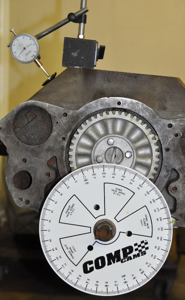
just an educated guess. You can sit down with a degree wheel and dial
indicator and determine everything you need to know to set up your
camshaft (click on photo to enlarge). The graph
shows the results from actual measurements with centerlines
calculated in a spreadsheet (available for
download). This
example is a pair of test lobes for our TilTech 220 Ford
flathead V8 cam (see Flathead Cams)
There is nothing magical about the numbers on the cam card or how
they were determined. The advance recommended by the cam grinder is probably
just an educated guess. You can sit down with a degree wheel and dial
indicator and determine everything you need to know to set up your
camshaft (click on photo to enlarge). The graph
shows the results from actual measurements with centerlines
calculated in a spreadsheet (available for
download). This
example is a pair of test lobes for our TilTech 220 Ford
flathead V8 cam (see Flathead Cams)
Finding TDC
The first step is to position the degree wheel and pointer accurately with respect to TDC. If you are building an engine with the head off, you determine TDC by first putting the dial indicator on top of the piston for the cylinder you're measuring. You can get a rough estimate by turning the crankshaft until the dial indicator shows the piston at it highest point. This is only a rough estimate of TDC due to lack of sensitivity, i.e. it takes several degrees of crankshaft rotation to show much change in piston position. To set TDC accurately, rotate the crankshaft until the piston is 0.200, 0.300 and 0.400 inches below TDC, both rising and falling. Record the crank angle reading at these six points and average them. This technique gives an accurate measure of TDC. Reposition the pointer accordingly. Note, the 0.200, 0.300 and 0.400 are not critical, just select three or four positions that are appreciably below TDC. If you are working with an engine that has the head on, you can use a dead stop which threads into the spark plug hole. TDC will be half way between the angles when you hit the stop by rotating from both directions.
Measuring the Lift Curve
Now you are ready to move the dial indicator to the cam. If its an overhead valve engine, I usually just put the dial indicator tip into the pushrod cup. If you have a flathead, you can just set it on top of the valve. Make absolutely certain there is no valve lash and the lifter is always in contact with the lobe. Also, make sure you always rotate the crankshaft in the clockwise direction (same as when it's running). Now, sit down in front of the engine with a pad and pencil. If you have a partner, type the numbers directly into a spreadsheet. Some people will tell you to record the lifts at specific crank angles; however, it's better to record the angles at specific lifts. With this procedure you can average the opening and closing angles to get the centerline (see blue points on graph). You can subtract the opening and closing numbers to get duration. You generally want a much finer scale during the opening portion of the profile, so you might use increments of 0.002 up to 0.020 lift, then use increments of 0.005, etc. and gradually work up to increments of 0.050 (see points on graph).
You should also check the cam for base circle runout by observing the movement of the dial indicator as the cam is rotated on the base circle. Ideally, the indicator should not move. In machinist lingo, that would be dead nuts on. A well ground cam should have no more than 0.001 inches of runout. Runout in excess of 0.002 indicates your cam was poorly ground. When you set the valve clearance for the cam, you might be on either a high spot or low spot, so the setting will be only as good as the base circle runout.
Analyzing the Data
There are software programs available for analyzing this data, but a spreadsheet works just as well. A sample spreadsheet is available on the download page. After you've entered the numbers into the spreadsheet, average the opening and closing angles to get an estimate of the centerline based on each lift point. If these numbers are uniform, the cam is symmetric. Asymmetric lobes usually have a different ramp design and lower acceleration on the closing side, but will generally be symmetric near the nose. The calculated centerlines are the blue points on the graph. There is a slight deviation in the numbers at low lifts, which is due to measurement error. Average the centerline numbers at the higher lifts (>0.10 or 0.20) to determine an accurate centerline (see labels on graph). Note, this procedure is the same as we used to determine TDC.
At least one intake lobe and its corresponding exhaust lobe should be measured. For the two lobes, the duration for this cam averaged 219.5 at 0.050 and 250.0 seat-to-seat (at 0.015), while the specs were 220 and 249. The lobe separation angle (in cam degrees) is half the difference of the lobe centerlines that you measured (in crankshaft degrees). For this example, the lobe separation in cam degrees is (107.8 + 112.4)/2 = 110.1, while the spec was 110. The advance for this example is 110.1 - 107.8 = 2.3 degrees. The purpose of these test lobes was to determine how to properly index the masters to get the correct advance for a production cam.
You can now compare these numbers to those for other similar engines or to the graphs on the Cam Performance page. If you have a cam card, you can compare your measurements with the specifications and evaluate the recommended cam advance. You can determine whether the cam is appropriate for your application by comparing it's duration with the information on the Cam Performance page. If the cam does not meet the specs you were given or if you were given incomplete specs and determine it is not appropriate for your application, you should return it.
If the cam advance you have determined from the measurements is not appropriate, you will need to adjust it. The method of adjustment varies from one engine to another. In some cases there are multiple sets of holes in the sprocket or gear. In other cases you may have to use an offset key or dowel pins. If you have a vernier sprocket or gear, the job will be easy. We prefer to set the cam using the intake centerline. Once you have made an adjustment, you will need to determine the new centerline. Determine the new centerline by measuring the opening and closing angles at lifts of say 0.20, 0.25 and 0.30. By averaging the six angles, you will have an accurate centerline.
 Knowing
the centerline, the opening and closing lift curves can be folded
and plotted on top of each other as in the graph at right. If you've used a spreadsheet in the calculations, it's easy to
calculate the velocity curve or the slope of the lift curve. Its best to use
central differencing, for example if the lift is 0.025 at -59.03 and
0.030 at -58.13, then the best estimate of velocity is :
Knowing
the centerline, the opening and closing lift curves can be folded
and plotted on top of each other as in the graph at right. If you've used a spreadsheet in the calculations, it's easy to
calculate the velocity curve or the slope of the lift curve. Its best to use
central differencing, for example if the lift is 0.025 at -59.03 and
0.030 at -58.13, then the best estimate of velocity is :
Velocity = (0.030 - 0.025)/(59.03 - 58.13) = 0.0056 at -58.58
where the -58.58 is the average of the two angles. The values for velocity can then be plotted. If the cam runs on flat tappets, the cam will run off the end of the tappet if the maximum velocity exceeds the tappet radius times (180/π). The Ford flathead V8 uses a one inch tappet, so the velocity must not exceed 0.00873 minus a margin of safety. For this example, the measurements are very close to the specified maximum velocity of 0.00829.
With a little practice, it is amazing how accurate one can get with a degree wheel and dial indicator. The velocity curve shows only a small amount of scatter. The graph clearly shows the constant velocity ramp and then the rapid acceleration on the flank. If we were to calculate acceleration by differencing the velocity curve, the results would have a lot of scatter. A cam profiler is needed to accurately measure acceleration and jerk.
Determining Valve Clearance
If you have solid lifters, you will also need to know the valve lash to use. How to Determine Valve Lash describes how to determine lash and describes a case where the cam card specified the wrong lash.