Camshaft Lobe Design
 Camshaft lobes are designed by starting with the lift curve, and
working backwards to determine the lobe shape that will produce
the lift curve. For this reason, we need to learn a bit more
about lift curves before we can discuss how lobes are designed.
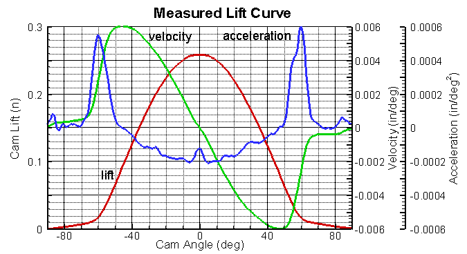
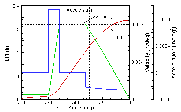
The graph at right shows the lift curve that was measured for a
stock Triumph TR4 camshaft. For cam design, not only is the
lift curve important, but also several derivatives of the curve.
The first derivative of the lift (slope of lift curve) is the
velocity measured in inches or mm per cam degree. Of
course, this is not a true velocity; however, if you multiply it by 6
times the camshaft speed (in RPM) you get the true velocity in
in/sec or mm/sec. The second derivative of the lift curve
(slope of velocity curve) is the acceleration in inches or
mm per degree2. The derivative of the acceleration
is called jerk. The derivative of jerk has several
different names, we prefer snap.
We can keep going and define crackle and pop as
well. These higher derivatives become increasingly esoteric.
The most important derivatives are the velocity, acceleration and
jerk. For a review of these concepts, check
Calculus 101.
Camshaft lobes are designed by starting with the lift curve, and
working backwards to determine the lobe shape that will produce
the lift curve. For this reason, we need to learn a bit more
about lift curves before we can discuss how lobes are designed.
The graph at right shows the lift curve that was measured for a
stock Triumph TR4 camshaft. For cam design, not only is the
lift curve important, but also several derivatives of the curve.
The first derivative of the lift (slope of lift curve) is the
velocity measured in inches or mm per cam degree. Of
course, this is not a true velocity; however, if you multiply it by 6
times the camshaft speed (in RPM) you get the true velocity in
in/sec or mm/sec. The second derivative of the lift curve
(slope of velocity curve) is the acceleration in inches or
mm per degree2. The derivative of the acceleration
is called jerk. The derivative of jerk has several
different names, we prefer snap.
We can keep going and define crackle and pop as
well. These higher derivatives become increasingly esoteric.
The most important derivatives are the velocity, acceleration and
jerk. For a review of these concepts, check
Calculus 101.
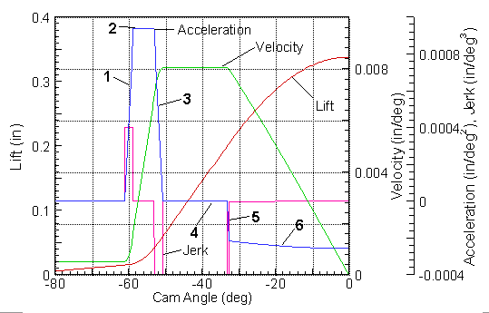
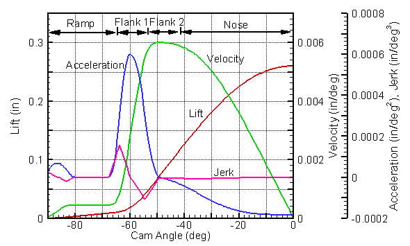 The
graph at left is a smoothed version of the one above with four areas
of the profile indicated. Since this cam is symmetric, only the left
side is plotted. The portions of the curve are: (1) constant
velocity ramp, (2) high acceleration flank, (3) low acceleration or
near constant velocity flank, and (4) nose. All cams will have
nose and high acceleration flanks. Probably all cams since 1930
have had ramps, usually with constant velocity. Some cams have a low acceleration portion on
the flank to give a near constant velocity, while some do not
have this feature.
The
graph at left is a smoothed version of the one above with four areas
of the profile indicated. Since this cam is symmetric, only the left
side is plotted. The portions of the curve are: (1) constant
velocity ramp, (2) high acceleration flank, (3) low acceleration or
near constant velocity flank, and (4) nose. All cams will have
nose and high acceleration flanks. Probably all cams since 1930
have had ramps, usually with constant velocity. Some cams have a low acceleration portion on
the flank to give a near constant velocity, while some do not
have this feature.
There are constraints on many of the lift curve parameters. For a flat tappet cam, the maximum velocity is limited by the diameter of the tappet. The maximum acceleration and minimum acceleration are limited by the valve springs, contact stresses (radius of curvature) and overall valve train compliance. Jerk also influences the valve train dynamics, but is of lesser importance than acceleration. Our discussion of valve springs shows the importance of acceleration. The discussion of valve train dynamics shows the importance of acceleration and jerk.
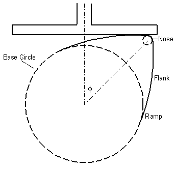 The
drawing at the right shows a cam lobe and lifter at 45 cam degrees.
The lift curve for this particular cam shows a velocity of 0.00595
in/deg at this position. Multiplying the velocity by (180/π)
gives the radial point of contact between the lifter and the lobe,
or 0.341 inches in this example. This relationship between the
lifter and point of contact limits the velocity for a flat lifter
cam. A safety factor is required to account for edge chamfer and possible
misalignment and cock of the lifter, so generally the velocity is
limited to:
The
drawing at the right shows a cam lobe and lifter at 45 cam degrees.
The lift curve for this particular cam shows a velocity of 0.00595
in/deg at this position. Multiplying the velocity by (180/π)
gives the radial point of contact between the lifter and the lobe,
or 0.341 inches in this example. This relationship between the
lifter and point of contact limits the velocity for a flat lifter
cam. A safety factor is required to account for edge chamfer and possible
misalignment and cock of the lifter, so generally the velocity is
limited to:
v < (π/180)(Rlifter - 0.025)
Roller cams do not have this limitation on velocity and that is their principal advantage. However, roller cams impose heavy restrictions on acceleration in order to avoid a lobe with convex flanks.
For a flat tappet cam, the radius of curvature is related to other cam parameters as follows:
Rc = Rb + L + a*(180/π)2
where Rb is the base circle radius, L is lift and a is acceleration. The base circle and lift are positive and their sum normally approximates the radius of the cam bearings. Acceleration is positive on the flank and negative at the nose. The nose radius must be large enough to prevent excessive contact stresses due to a small nose radius. This requirement indirectly limits the magnitude of deceleration at the nose. The nose deceleration is also the most important parameter determining the size of the valve springs.
The velocity, acceleration and deceleration rates, and jerk all have some approximate limiting values. Positive acceleration and jerk do not have hard and fast limits, so valve train dynamics or physical experimentation may be required to establish firm limits. For purposes of lobe design we assume we know the limits and wish to design the best lobe within those constraints.
The methods used to design cam profiles are often closely guarded company secrets. It seems those that guard their methods most closely, like to refer to them only as "modern". Most likely, they are using polynomial design methods that are over 60 years old. Nevertheless, enough sketchy information is available to follow the general trends of usage. The most popular methods for designing cam profiles has changed over the years. The early design methods are discussed on the Cam Design History page, while currently used methods are described here.
The most important deficiency of some of the early design methods is that they gave jump discontinuities in acceleration, i.e. infinite jerk. Infinite jerk tends to trigger vibrations in the valve train. Most engines prior to 1950, especially those in the US, were flatheads (side valve, L head) and relatively slow turning, < 4500 RPM. A flathead valve train is very stiff. Harmonic profiles with infinite jerk were not a problem with these engines. When higher revving OHV engines appeared cam profiles with infinite jerk fell from favor (see Jerk is it Important?).
After methods with infinite jerk were abandoned in the early 1950's, the most popular method seems to have become methods based on incomplete polynomials. Although some might refer to this as a "modern" design method, the idea has been around for more than 60 years. (see Dudley). The equation below is typical of the type used by these methods.
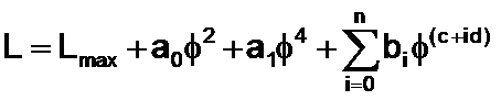
Usually n = 2 or 3. 2a0 is the value for acceleration and 24a1 is the value for snap at φ = 0, so inclusion of these parameters helps to provide a nose of proper shape. Some of the other parameters are specified by endpoint conditions, while the others are chosen by the designer. The exponents, c + id, are generally quite large, usually > 10. Typical values might be 10, 12 and 14 or 12, 16, 18. We call this an incomplete polynomial, because unlike a normal polynomial approximation, it skips intermediate values of the exponents. This method has a number of deficiencies. It is difficult to use until the designer develops some experience, because he is forced to choose design parameters, polynomial exponents, that have no clear connection to the physical system. Consequently, imposing limits on velocity, acceleration and jerk is difficult. The method does not provide enough flexibility in the choice of shape. Despite these limitations, this method is still widely used, because it is simple to apply.
More recently, splines have also been used to develop cam profiles. We were surprised to learn that the earliest references for their use in cam design is in 1985 (see McCarthy and Burns). Splines are the mathematical equivalent of a french curve. They provide almost unlimited flexibility. In fact, as they are normally applied, they provide too much flexibility. Splines represent the lift curve as a number of functions, usually polynomials, that are pieced together. The designer divides the domain into subintervals by specifying a series of "knots" at various cam angles. The profile is represented as a polynomial within each subinterval. Depending on the order of the spline, various derivatives are matched at the knots where two polynomials come together. For example, the simplest spline uses quadratic polynomials, with first derivatives matched at the knots. A quadratic spline will have a discontinuity in the second derivatives at the knots. This means velocity will be continuous, but acceleration will have jumps at the knots, i.e. infinite jerk. A cubic spline (3rd degree) has continuous second derivatives (acceleration) and a quartic spline (4th degree) has continuous third derivatives (jerk). A quintic spline (5th degree) has continuous snap, etc.
Splines are a definite improvement over polynomial lift curves, but the normal method of application is cumbersome for the designer. He has almost too much flexibility. He must first select the number and location of the knots. Experience is required to make this selection effectively. He must then assign values of the lift parameters at the knots. The problem is inherently underspecified, i.e. there are more unknowns than equations or specifications. It would be much better if the designer could just say "design a cam with the following limits on lift, velocity, acceleration and jerk". We will outline how to do this. However, we first describe an innovative method that has been forgotten.
 The curves at the right are for aTriple
Curve Contour as presented in 1934 (see
Bouvy, Turkish). This method can be classified as a spline
method, although it has never been described that way previously.
It represents the lift curve by a combination of quadratic splines
and an harmonic nose. Consequently, for the quadratic
intervals, the velocity is linear and the acceleration is constant.
An important feature is that it allows the designer to directly
impose constraints on the acceleration and velocity. A key
difference between this and most spline techniques is that
the knot locations are determined during the calculation, they are
not preselected.
The curves at the right are for aTriple
Curve Contour as presented in 1934 (see
Bouvy, Turkish). This method can be classified as a spline
method, although it has never been described that way previously.
It represents the lift curve by a combination of quadratic splines
and an harmonic nose. Consequently, for the quadratic
intervals, the velocity is linear and the acceleration is constant.
An important feature is that it allows the designer to directly
impose constraints on the acceleration and velocity. A key
difference between this and most spline techniques is that
the knot locations are determined during the calculation, they are
not preselected.
The Triple Curve method is conceptually quite simple. Assume the duration, maximum velocity, acceleration and deceleration are given. The width of the acceleration flank and the nose are calculated from the maximum velocity. The total width is specified by the duration, so the width of the constant velocity flank is gotten by difference. This calculation will give the maximum lift for the given set of constraints together with an harmonic nose. A constant deceleration nose with the same deceleration limit will give slightly more lift, but a smaller minimum radius of curvature and higher contact stresses. If the lift is constraining, then one of the other constraints is relaxed. The method was described only for the case with a constant velocity flank. If the duration is short or the tappet diameter is large there will be no dwell at the maximum velocity, so a simple iterative solution is required to determine the point of reversal in acceleration.
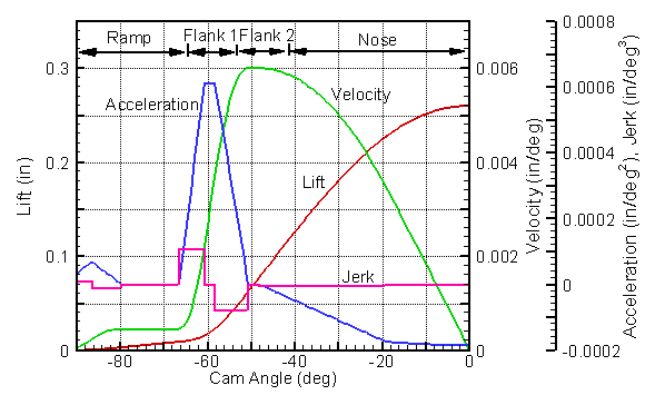
The Triple Curve method was used by Ford starting in the late 1940's (see History). The curves at the above right are for the 1949-51 Mercury flathead V8 (designated as 8CM). Hollingsworth and Hodges describe the same method, but they called it KCARC. It appears that Cosworth also used constant acceleration profiles.
The Triple Curve method meets almost all of our requirements, since it allows us to directly specify constraints on velocity, acceleration and deceleration. Its only deficiency is that it has infinite jerk at the knots. In a short paragraph at the end of his article in 1934, Bouvy gives a brief description of an extension with finite jerk. He simply replaced the jumps in acceleration by a blend region with linear acceleration or constant jerk. This extension to cubic splines is conceptually simple and it gives exactly the characteristics we want, i.e. the direct imposition of constraints on velocity, acceleration and jerk. This representation also provides the necessary smoothness from theoretical considerations (see Norton). Unfortunately, the method was not adopted by others and was largely forgotten until we developed it independently in 2002. We have extended and generalized the method from that presented by Bouvy. For example, if the designer prefers an even smoother curve, a blend composed of two functions with linear jerk can be used to give a quartic spline and continuous jerk. The curve below left is the 1949 Mercury 8CM cam (above right), modified with maximum jerk constrained to 0.0004 (in/deg3) using cubic splines. The curve below right is the 8CM cam modified with quartic splines and maximum jerk of 0.0004.
 Remember,
the ideal cam would open and close instantaneously, and this method
comes as close as possible to that ideal given the specified
constraints. To demonstrate, follow the numbered areas on
acceleration curve above left - (1) after leaving the opening ramp,
increase the acceleration as quickly as allowed by the constraint on
jerk, (2) maintain the acceleration at its maximum allowed value,
(3), decrease the acceleration as quickly as possible so the maximum
velocity and zero acceleration are reached at the same point, (4)
maintain the velocity at its maximum value (zero acceleration), (5) decrease the
acceleration as quickly as possible to match the nose acceleration
(deceleration) (6) decelerate as quickly as permitted by the maximum
deceleration constraint over a period to give zero velocity at the nose.
This approach will give the maximum lift and area for a
given set of constraints.
Remember,
the ideal cam would open and close instantaneously, and this method
comes as close as possible to that ideal given the specified
constraints. To demonstrate, follow the numbered areas on
acceleration curve above left - (1) after leaving the opening ramp,
increase the acceleration as quickly as allowed by the constraint on
jerk, (2) maintain the acceleration at its maximum allowed value,
(3), decrease the acceleration as quickly as possible so the maximum
velocity and zero acceleration are reached at the same point, (4)
maintain the velocity at its maximum value (zero acceleration), (5) decrease the
acceleration as quickly as possible to match the nose acceleration
(deceleration) (6) decelerate as quickly as permitted by the maximum
deceleration constraint over a period to give zero velocity at the nose.
This approach will give the maximum lift and area for a
given set of constraints.
The maximum jerk of 0.0004 (in/deg3) used above is within the guidelines recommended by Hollingsworth and Hodges. These curves with finite jerk were created with the same 0.050 duration as the original profile. The increased smoothness decreases the total lift by only 0.0002 inches. However, the duration at 0.015 (seat-to-seat) increases from 240 degrees to 244.3 and 248.6 degrees for cubic and quartic cams, respectively. This increased seat-to-seat duration will have a negative impact on performance (see Cam Performance - Opening Rate). We prefer the cubic spline method, since it provides the necessary smoothness, but without creating a slow opening or low lift cam and a loss of performance. We believe engine performance gains can be achieved using this design method with appropriate smoothness, because most "performance" cams today are smoother than necessary (see Jerk is it Important?).
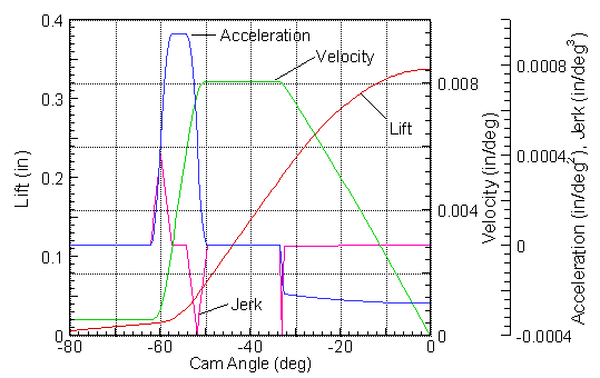
 The
smoothed lift curve for the Triumph TR4 (second
figure from top of the page) is an example of a more complex profile
represented with quartic splines. A quartic spline
representation is used together with an harmonic nose, so jerk is
continuous.
The figure at left is the same profile represented with cubic
splines and an harmonic nose. The lift for the cubic and
quartic spline representations differs by a maximum of 0.00027
inches. There are no visible
differences in the other curves, except in the jerk and at the peak of acceleration.
Not surprisingly, valve train dynamic calculations with these two
representations give nearly identical results. The maximum
jerk for these two profiles, matched to the same cam, are 0.00011 and
0.00016 for the cubic and quartic representations, respectively.
We find that larger maximum jerks can be used with the quartic cams
to achieve the same valve train dynamics.
The
smoothed lift curve for the Triumph TR4 (second
figure from top of the page) is an example of a more complex profile
represented with quartic splines. A quartic spline
representation is used together with an harmonic nose, so jerk is
continuous.
The figure at left is the same profile represented with cubic
splines and an harmonic nose. The lift for the cubic and
quartic spline representations differs by a maximum of 0.00027
inches. There are no visible
differences in the other curves, except in the jerk and at the peak of acceleration.
Not surprisingly, valve train dynamic calculations with these two
representations give nearly identical results. The maximum
jerk for these two profiles, matched to the same cam, are 0.00011 and
0.00016 for the cubic and quartic representations, respectively.
We find that larger maximum jerks can be used with the quartic cams
to achieve the same valve train dynamics.This spline method is so simple and effective it is surprising it has not been used before. Our Opticam Software™ uses this design method with a choice of either cubic (continuous acceleration) or quartic (continuous jerk) approximations. Although the method is conceptually simple, the implementation was not. Difficulties arise when one or more constraints is not effective, so one or more of the various regions disappear. For example, if the tappet is large or the duration is short, there will be no dwell at maximum velocity. If the jerk is small or the maximum acceleration constraint is large, there will be no dwell at maximum acceleration. Disappearance of the dwell at maximum velocity can give rise to just an inflection point in the acceleration curve, see the Triumph TR4 profile above for example. The method is quite flexible. We have yet to find a measured profile that cannot be accurately fit with this spline approximation.